
تعيين مقاومة مجهولة باستخدام قانون أومDetermination of an Unknown Resistance from the Slope of the V–I Graph
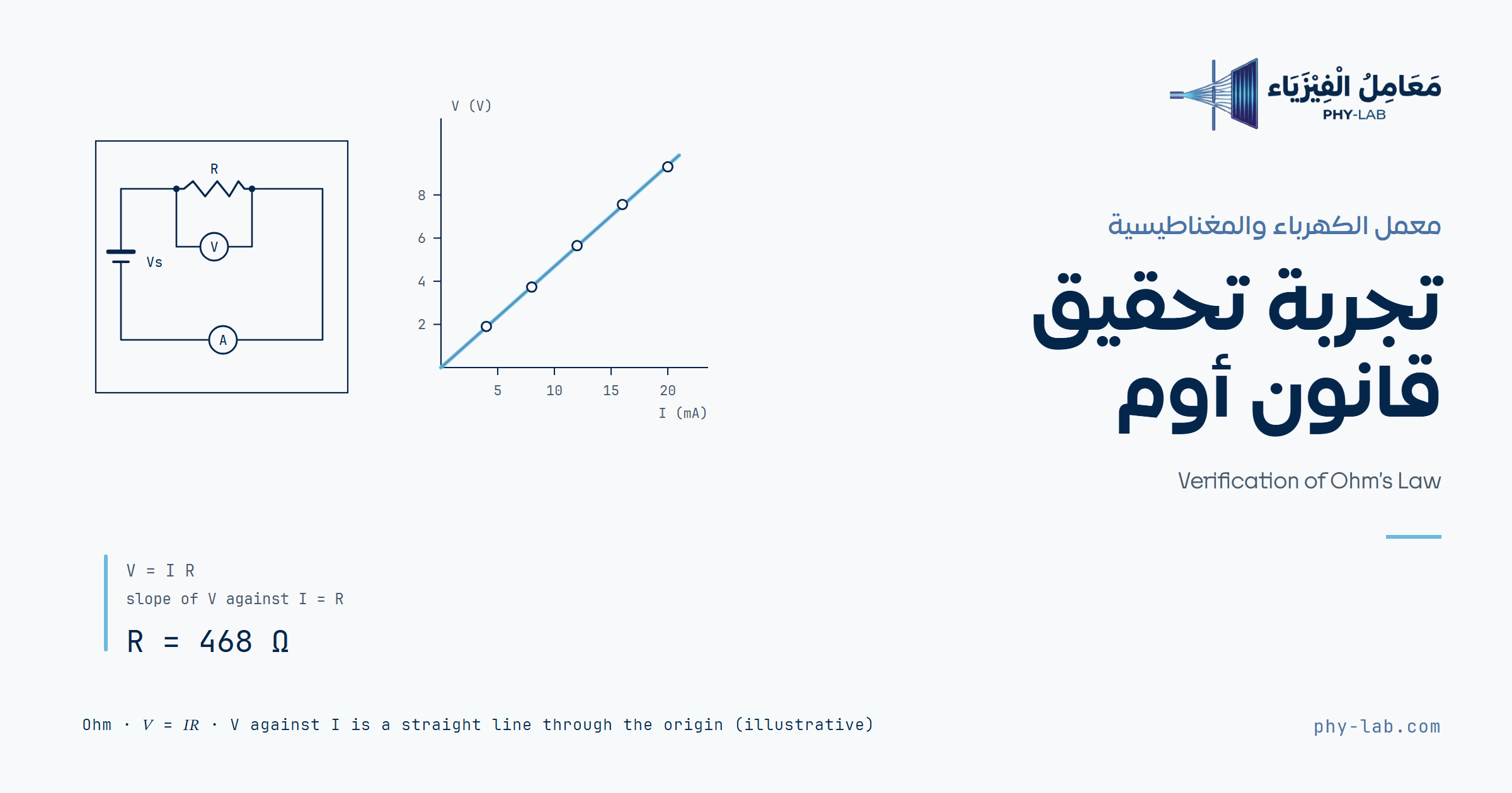
تُطبَّق جهود مختلفة على مقاومة مجهولة، ويُقاس التيار المار فيها عند كل جهد. ثم يُرسم الجهد V على المحور الرأسي والتيار I على المحور الأفقي، فينتج خط مستقيم ميله يساوي المقاومة R.Different voltages are applied to an unknown resistance, and the current through it is measured at each voltage. The voltage V is then plotted on the vertical axis against the current I on the horizontal axis, giving a straight line whose slope equals the resistance R.
الهدف والأجهزةObjective and apparatus
- تعيين قيمة مقاومة مجهولة من ميل منحنى الجهد والتيار.
- To determine the value of an unknown resistance from the slope of the voltage–current graph.
- مصدر جهد مستمر: يزوّد الدائرة بجهد قابل للضبط.
- ملتيميتر (فولتميتر): يقيس فرق الجهد، ويوصَل على التوازي مع المقاومة.
- ملتيميتر (أميتر): يقيس التيار، ويوصَل على التوالي مع المقاومة.
- مقاومة مجهولة: العنصر المراد تعيين قيمته.
- لوح توصيل وأسلاك: لتركيب الدائرة.
- DC voltage supply: supplies the circuit with an adjustable voltage.
- Multimeter (voltmeter): measures the potential difference, and is connected in parallel with the resistance.
- Multimeter (ammeter): measures the current, and is connected in series with the resistance.
- Unknown resistance: the element whose value is to be found.
- Breadboard and leads: to build the circuit.
الأساس النظريTheory
قانون أومOhm’s law
ينص قانون أوم على أن فرق الجهد V بين طرفي موصل يتناسب طردياً مع التيار I المار فيه، وثابت التناسب هو مقاومة الموصل R:
Ohm’s law states that the potential difference V across a conductor is directly proportional to the current I through it, and the constant of proportionality is the resistance R of the conductor:
V فرق الجهد بين طرفي المقاومة بالفولت (V)، وI التيار المار فيها بالأمبير (A)، وR المقاومة بالأوم (Ω)، حيث 1 Ω = 1 V/A.
V is the potential difference across the resistance in volts (V), I the current through it in amperes (A), and R the resistance in ohms (Ω), where 1 Ω = 1 V/A.
المقاومة من ميل الخط المستقيمThe resistance from the slope of the straight line
المعادلة (1) على صورة معادلة خط مستقيم y = m x. فإذا رُسم V على المحور الرأسي وI على المحور الأفقي، كان الناتج خطاً مستقيماً يمر بنقطة الأصل، وميله m يساوي المقاومة:
Equation (1) has the form of a straight line y = m x. If V is plotted on the vertical axis and I on the horizontal axis, the result is a straight line through the origin, and its slope m equals the resistance:
عند حساب الميل يدوياً تُختار نقطتان على الخط المرسوم نفسه، لا من نقاط الجدول، وتكونان متباعدتين قدر الإمكان لتقليل خطأ القراءة من الرسم. أما الأداة فتحسب الميل بطريقة المربعات الصغرى التي تمرر أفضل خط مستقيم بين جميع النقاط:
When the slope is found by hand, two points are taken on the drawn line itself, not from the table, and as far apart as possible to reduce the error of reading the graph. The tool computes the slope by least squares, which passes the best straight line through all the points:
حيث N عدد القراءات. ويُقدَّر عدم اليقين في الميل من تشتت النقاط حول الخط:
where N is the number of readings. The uncertainty in the slope is estimated from the scatter of the points about the line:
حيث D مقام المعادلة (3)، وb نقطة تقاطع الخط مع محور الجهد. ونظرياً يجب أن تكون b قريبة من الصفر.
where D is the denominator of equation (3), and b is the intercept of the line on the voltage axis. In theory b should be close to zero.
أثر الفولتميترThe effect of the voltmeter
والفولتميتر الموصول على التوازي يسحب تياراً صغيراً، فالأميتر يقيس تيار المقاومة والفولتميتر معاً، ويكون الميل مقاومتهما على التوازي لا R وحدها. فإذا عُرفت مقاومة الفولتميتر RV صُحّح الميل:
The voltmeter in parallel draws a small current, so the ammeter measures the current of the resistance and the voltmeter together, and the slope is their parallel resistance rather than R alone. If the voltmeter resistance RV is known, the slope is corrected:
ومقاومة الملتيميتر الرقمي نحو 10 MΩ فأثره صغير جداً، أما الفولتميتر ذو المؤشر فمقاومته أصغر بكثير، وأثره ظاهر مع المقاومات الكبيرة.
A digital multimeter has about 10 MΩ, so its effect is very small, while a pointer voltmeter has a much smaller resistance, and its effect shows with large resistances.
خطوات التجربةProcedure
- صِل الدائرة كما في الشكل 1 والمصدر مطفأ ومضبوط على الصفر، واطلب من المشرف مراجعة التوصيل.
- شغّل المصدر وارفع الجهد إلى 2 V، ثم سجّل قراءة الفولتميتر وقراءة الأميتر.
- كرر القياس عند 4 و6 و8 و10 و12 V، وسجّل كل زوج من القراءات في جدول البيانات.
- ارسم V على المحور الرأسي وI على المحور الأفقي، واحسب الميل لتحصل على قيمة المقاومة.
- أعد المصدر إلى الصفر وأطفئه قبل فك الدائرة.
- Connect the circuit as in figure 1 with the supply off and set to zero, and ask the supervisor to check the connections.
- Switch the supply on and raise the voltage to 2 V, then record the voltmeter reading and the ammeter reading.
- Repeat the measurement at 4, 6, 8, 10 and 12 V, and record each pair of readings in the data table.
- Plot V on the vertical axis against I on the horizontal axis, and compute the slope to obtain the value of the resistance.
- Return the supply to zero and switch it off before taking the circuit apart.
احتياط: اختر مدى الأميتر المناسب قبل التشغيل، ولا تغيّر توصيل الدائرة والمصدر يعمل.
Precaution: choose a suitable ammeter range before switching on, and do not change the circuit connections while the supply is on.
أخطاء شائعةCommon errors
- مدى أميتر غير مناسب: المدى الكبير جداً يعطي قراءات بخانات قليلة، والصغير جداً يخرج عن المدى.
- خلط وحدات التيار: إدخال قراءات بالمللي أمبير على أنها بالأمبير يجعل المقاومة أصغر ألف مرة.
- تبديل المحورين: رسم I على المحور الرأسي يعطي ميلاً يساوي 1/R لا R.
- إهمال مقاومة الفولتميتر: مع مقاومة كبيرة وفولتميتر ذي مؤشر يخرج الميل أصغر من R بوضوح.
- الميل من نقطتين من الجدول: يتأثر بخطأ هاتين القراءتين وحدهما، أما أفضل خط فيستعمل القراءات كلها.
- An unsuitable ammeter range: a range that is too large gives readings with few digits, and one that is too small goes over range.
- Mixing current units: entering readings in milliamperes as if they were in amperes makes the resistance a thousand times smaller.
- Swapping the axes: plotting I on the vertical axis gives a slope equal to 1/R, not R.
- Ignoring the voltmeter resistance: with a large resistance and a pointer voltmeter the slope comes out clearly smaller than R.
- The slope from two table points: it depends on the error of these two readings alone, while the best line uses all the readings.
المحاكاة التفاعليةInteractive simulation
اختر المقاومة المجهولة ومدى الأميتر ونوع الفولتميتر والمصدر مطفأ، ثم شغّل المصدر واضبط جهده بالأزرار، وسجّل القراءتين عند كل جهد.
Choose the unknown resistance, the ammeter range and the voltmeter type with the supply off, then switch the supply on, set its voltage with the buttons, and record the two readings at each voltage.
قيم يحددها المعلمValues set by the teacher
اكتب قيمة كل مقاومة واختر وحدتها والمصدر مطفأ، ثم اضغط «اعتمد القيم». ويحسب فحص السلامة تحت المحاكاة التيار والقدرة قبل التشغيل، فتحقق منهما بيدك قبل أن توصل الجهاز.
Write the value of each resistor and choose its unit with the supply off, then press “Apply the values”. The safety check below the simulation computes the current and the power before switching on; check them by hand before connecting the meter.
النموذج: ثلاث مقاومات قيمها مخفية، ومصدر بمقاومة داخلية صغيرة، وأميتر بثلاثة مديات لكل منها مقاومة داخلية ودقة عرض، وفولتميتر رقمي بمقاومة كبيرة أو فولتميتر ذو مؤشر بمقاومة أصغر، مع ضجيج صغير في القراءات. المحاكاة نموذج لا قياس.Model: three resistances with hidden values, a supply with a small internal resistance, an ammeter with three ranges each with its own internal resistance and display resolution, and a digital voltmeter with a large resistance or a pointer voltmeter with a smaller one, with a small noise in the readings. The simulation is a model, not a measurement.
وعند اختيار «يحددها المعلم» تنحرف القيمة الحقيقية للمقاومة عن المكتوبة بأقل من 1.5 %، كما في المقاومات الحقيقية.With “Set by the teacher”, the true value of the resistance differs from the written one by less than 1.5 %, as in real resistors.
إدخال البياناتData entry
أدخل قراءات الجهد والتيار، ثلاث قراءات على الأقل بتيارات مختلفة. ومقاومة الفولتميتر اختيارية؛ لتصحيح الميل بالمعادلة (6).
Enter the voltage and current readings, at least three readings with different currents. The voltmeter resistance is optional; it corrects the slope by equation (6).
جدول البياناتData table
| رقمNo | V (V) | I (mA) |
|---|
البيانات الحالية توضيحية من نموذج المحاكاة؛ وليست قياساً.Current data are illustrative, from the simulation model; not a measurement.
لصق بيانات أو تحميل ملف CSVPaste data or load a CSV file
سطر لكل قراءة: V بالفولت ثم I بوحدة التيار المختارة، تفصل بينهما فاصلة أو مسافة.
One line for each reading: V in volts then I in the chosen current unit, separated by a comma or a space.
النتائجResults
خطوات الحلSolution steps
التفسيرInterpretation
إجابات أسئلة المناقشة من بياناتكAnswers to the discussion questions from your data
أسئلة المناقشةDiscussion questions
- هل النقاط على خط مستقيم؟ ماذا يدل ذلك على العلاقة بين الجهد والتيار في المقاومة؟
- هل يمر الخط بنقطة الأصل؟ وإن لم يمر، فما السبب المحتمل؟
- احسب الميل يدوياً من نقطتين على الخط المرسوم، وقارنه بالقيمة التي حسبتها الأداة.
- لماذا نعيّن المقاومة من الميل بدلاً من حساب V/I لقراءة واحدة فقط؟
- لو استُبدلت المقاومة بأخرى قيمتها الضعف، كيف يتغير ميل الخط؟
- Do the points lie on a straight line? What does that say about the relation between the voltage and the current in the resistance?
- Does the line pass through the origin? If not, what is the likely reason?
- Compute the slope by hand from two points on the drawn line, and compare it with the value computed by the tool.
- Why is the resistance found from the slope rather than from V/I for a single reading?
- If the resistance were replaced by one twice as large, how would the slope of the line change?
بعد حساب النتائج تظهر إجابة كل سؤال بأرقام قياساتك في قسم النتائج.
After the results are computed, the answer to each question appears with the numbers of your measurements in the results section.
المراجعReferences
- Serway, R. A., & Jewett, J. W. (2018). Physics for scientists and engineers (10th ed.). Cengage Learning.
- Taylor, J. R. (1997). An introduction to error analysis: The study of uncertainties in physical measurements (2nd ed.). University Science Books.