تعيين الطول الموجي لشعاع الليزر بالمونوكروماتور
Laser Beam Wavelength by a Monochromator


تعيين الطول الموجي لشعاع الليزر بالمونوكروماتورLaser Beam Wavelength by a Monochromator
أدِر محزوز المونوكروماتور حول خط الليزر وسجّل قراءة الفولتميتر V كل 0.2 nm، وتحسب الأداة V/Vmax والطول الموجي عند أكبر شدة وعرض الخط عند نصف القمة FWHM لمصدرين مع عدم اليقين وخطوات الحل.Turn the monochromator grating across the laser line and record the voltmeter reading V every 0.2 nm, and the tool computes V/Vmax, the wavelength of maximum intensity and the full width at half maximum (FWHM) for two sources, with their uncertainty and the solution steps.
الهدف والأجهزةObjective and apparatus
قياس الطول الموجي لشعاع ليزر معطى باستعمال المونوكروماتور (الموحِّد اللوني)، وتعيين عرض خطه الطيفي عند نصف القمة FWHM، لمصدرين ليزريين:
To measure the wavelength of a given laser beam using a monochromator, and to determine the full width at half maximum (FWHM) of its spectral line, for two laser sources:
- مصدرا ليزر (مصدر #1 ومصدر #2)
- مونوكروماتور بمحزوز حيود وشقّي دخول وخروج وقرص لقراءة الطول الموجي
- مقعد بصري بحوامل
- كاشف ضوئي (خلية ضوئية)
- فولتميتر
- Two laser sources (source #1 and source #2)
- Monochromator with a diffraction grating, entrance and exit slits and a wavelength dial
- Optical bench with stages and holders
- Optical detector (photocell)
- Voltmeter
الأساس النظريTheory
يفصل المونوكروماتور جزءاً ضيقاً من الطيف الداخل إليه. يدخل الضوء من شق الدخول، فتجعله مرآة مقعرة حزمة متوازية تسقط على محزوز حيود، ثم تجمع مرآة ثانية الضوء المحاد على شق الخروج. يحيد المحزوز كل طول موجي بزاوية مختلفة وفق معادلة المحزوز:
A monochromator separates a narrow part of the spectrum that enters it. Light enters through the entrance slit, a concave mirror makes it a parallel beam that falls on a diffraction grating, and a second mirror focuses the diffracted light on the exit slit. The grating diffracts each wavelength at a different angle according to the grating equation:
حيث d المسافة بين خطوط المحزوز، وα وβ زاويتا السقوط والحيود، وm رتبة الحيود. في تركيب Czerny–Turner تبقى الزاوية بين الحزمتين الداخلة والخارجة ثابتة 2φ، فتدوير المحزوز بزاوية θ يختار الطول الموجي الذي يمر من شق الخروج، والقرص مدرَّج بهذا الطول مباشرة:
where d is the grating spacing, α and β are the angles of incidence and diffraction, and m is the diffraction order. In the Czerny–Turner layout the angle between the incoming and outgoing beams stays fixed at 2φ, so rotating the grating by an angle θ selects the wavelength that passes the exit slit, and the dial is graduated directly in that wavelength:
تنتقل صورة شق الدخول على مستوى شق الخروج حين يتغير الطول الموجي؛ ومقدار التغير في الطول الموجي لكل مليمتر هو التشتت الخطي العكسي، حيث f البعد البؤري للمرآة الثانية:
The image of the entrance slit moves across the exit-slit plane when the wavelength changes; the change in wavelength per millimetre is the reciprocal linear dispersion, where f is the focal length of the second mirror:
لهذا يخرج من شق الخروج مدى من الأطوال الموجية لا طول واحد، يُسمّى عرض النطاق ويتناسب مع عرض الشقين w (وهما متساويان). وعند مسح خط ضيق جداً كالليزر يكون المنحنى الناتج مثلثياً تقريباً، عرضه عند نصف القمة:
So a range of wavelengths leaves the exit slit, not a single one; it is called the bandpass and is proportional to the slit width w (both slits are equal). When a very narrow line such as a laser is scanned, the resulting curve is nearly triangular, with a full width at half maximum of:
قراءة الفولتميتر تتناسب مع شدة الضوء الواقع على الكاشف، فالقسمة على أكبر قراءة تعطي الشدة النسبية. يؤخذ الطول الموجي لليزر عند القمة، ويُحسب الطولان λ₋ وλ₊ عند نصف القمة بالاستيفاء الخطي بين القراءتين اللتين تحيطان بالقيمة ½:
The voltmeter reading is proportional to the intensity on the detector, so dividing by the largest reading gives the relative intensity. The laser wavelength is taken at the peak, and the two wavelengths λ− and λ+ at half maximum are found by linear interpolation between the two readings on either side of ½:
العرض المقيس مزيج من عرض الخط الحقيقي وعرض الجهاز، وبتقريب غاوسي:
The measured width combines the true line width and the instrument width; in the Gaussian approximation:
عرض خط ليزر الهيليوم نيون نحو 0.002 nm أو أقل، وهو أصغر كثيراً من عرض نطاق مونوكروماتور تعليمي (عُشر نانومتر إلى بضعة نانومترات)؛ لذلك فالـ FWHM المقيس في هذه التجربة هو عرض نطاق الجهاز عملياً، ويصغر بتضييق الشقين. ومن الطول الموجي تُحسب طاقة الفوتون وقدرة التحليل:
The line width of a helium–neon laser is about 0.002 nm or less, far smaller than the bandpass of a teaching monochromator (a tenth of a nanometre to a few nanometres); so the FWHM measured here is practically the instrument bandpass, and it shrinks when the slits are narrowed. From the wavelength the photon energy and the resolving power follow:
إذا كان للكاشف قراءة في الظلام V₀ (الليزر محجوب) فالأدق أن تُطرح من كل القراءات قبل القسمة: r = (V − V₀)/(Vmax − V₀)؛ وإلا ظهر مستوى نصف القمة أعلى مما يجب وصغر العرض المحسوب.
If the detector gives a reading in the dark V₀ (laser blocked), it is more accurate to subtract it from all readings before dividing: r = (V − V₀)/(Vmax − V₀); otherwise the half-maximum level appears higher than it should and the computed width is too small.
خطوات التجربةProcedure
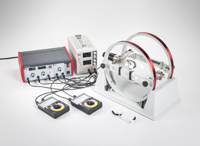
- صِل الأجهزة كما في الشكل 2 باستعمال مصدر الليزر الأول.
- وجّه شعاع الليزر إلى شق الدخول في المونوكروماتور.
- أدِر محزوز المونوكروماتور عبر مدى الأطوال الموجية للون الليزر حتى ترى الشعاع خارجاً من شق الخروج.
- وجّه الشعاع الخارج من المونوكروماتور إلى مدخل الكاشف.
- ابحث عن أكبر شدة Imax لشعاع الليزر (أكبر شدة تقابل أكبر قراءة للفولتميتر، لأن قراءته تتناسب مع شدة الشعاع)، وسجّل طولها الموجي (وليكن x nm).
- أدِر المحزوز إلى الطول الموجي x − 3 nm، وابدأ تسجيل شدة الشعاع الخارج (قراءة الفولتميتر) بخطوات 0.2 nm حتى تصل إلى x + 3 nm.
- دوّن بياناتك في الجدول 1.
- عيّن من القراءات أكبر قراءة للجهد Vmax واقسم عليها جميع القراءات.
- ارسم منحنى العلاقة بين الطول الموجي (على المحور السيني) والنسبة V/Vmax (على المحور الصادي).
- قِس العرض عند نصف القمة FWHM لخط الليزر: اقسم أكبر نسبة على اثنين (V/Vmax/2)، وعيّن الطولين الموجيين λ₊ وλ₋ المقابلين لها، ثم احسب FWHM = λ₊ − λ₋.
- كرّر جميع الخطوات السابقة لمصدر الليزر الثاني.
- Connect the equipment as shown in figure 2 using the first laser source.
- Align the laser beam to the entrance slit of the monochromator.
- Turn the monochromator grating through the wavelength range of the laser colour until you see the beam leaving the exit slit.
- Align the beam leaving the monochromator to the entrance of the detector.
- Search for the maximum intensity Imax of the laser beam (maximum intensity corresponds to the maximum voltmeter reading, since the reading is proportional to the beam intensity) and record its wavelength (say x nm).
- Turn the grating to the wavelength x − 3 nm and start recording the exiting beam intensity (voltmeter reading) in steps of 0.2 nm until you reach x + 3 nm.
- Tabulate your data in table 1.
- From the readings find the maximum voltage reading Vmax and divide all the readings by it.
- Draw a curve of the wavelength (on the x-axis) against the ratio V/Vmax (on the y-axis).
- Measure the full width at half maximum (FWHM) of the laser line: divide the maximum ratio by two (V/Vmax/2), find the two wavelengths λ+ and λ− corresponding to it, then compute FWHM = λ+ − λ−.
- Repeat all the above steps for the second laser source.
الأطوال الموجية بالنانومتر كما تُقرأ على قرص المونوكروماتور، والجهد بالفولت. لا تغيّر عرض الشقين بين المصدرين حتى تكون المقارنة عادلة، واقترب من كل قراءة من الاتجاه نفسه لتجنب ارتداد آلية القرص.
Wavelengths are in nanometres as read on the monochromator dial, and the voltage in volts. Do not change the slit width between the two sources so the comparison is fair, and approach every reading from the same direction to avoid backlash in the dial mechanism.
المحاكاة التفاعليةInteractive simulation
اختر المصدر، ثم أدِر القرص بالمنزلق (أو اسحب داخل المونوكروماتور) حتى تقترب بقعة الليزر من شق الخروج وتظهر قراءة على الفولتميتر. ابحث عن أكبر قراءة، ثم ارجع 3 nm وسجّل بزر «سجّل ثم +0.2» حتى تتجاوز القمة بـ 3 nm. تذهب كل قراءة إلى جدول المصدر المختار. الطول الموجي الحقيقي لليزر ومعايرة القرص غير معروضين، والمطلوب تعيين الطول الموجي.
Choose the source, then turn the dial with the slider (or drag inside the monochromator) until the laser spot approaches the exit slit and the voltmeter shows a reading. Find the largest reading, then go back 3 nm and record with the “Record, then +0.2” button until you pass the peak by 3 nm. Each reading goes to the table of the selected source. The true laser wavelength and the dial calibration are not shown; finding the wavelength is the task.
النموذج: مونوكروماتور Czerny–Turner بمحزوز 1200 خط/mm وشقين متساويين؛ صورة شق الدخول تتحرك على شق الخروج مع تدوير القرص، والقراءة تتناسب مع الجزء المار منها (منحنى مثلثي ينعّمه زيغ بسيط)، مع قراءة ظلام صغيرة وتشويش. الحجم الظاهر للبقعة مكبَّر ليُرى. المحاكاة نموذج لا قياس.Model: a Czerny–Turner monochromator with a 1200 lines/mm grating and two equal slits; the image of the entrance slit moves across the exit slit as the dial turns, and the reading is proportional to the part that passes (a triangular curve smoothed by a small aberration), with a small dark reading and noise. The spot is drawn enlarged to be seen. The simulation is a model, not a measurement.
إدخال البياناتData entry
الجدول 1: لكل مصدر الطول الموجي على القرص λ بالنانومتر وقراءة الفولتميتر V، وتُحسب V/Vmax تلقائياً. يمكن ملء جدول مصدر واحد فقط.
Table 1: for each source the dial wavelength λ in nanometres and the voltmeter reading V; V/Vmax is computed automatically. Filling the table of one source only is allowed.
| المصدرSource #1 | ||
|---|---|---|
| λ (nm) | V (V) | V/Vmax |
| المصدرSource #2 | ||
|---|---|---|
| λ (nm) | V (V) | V/Vmax |
البيانات الحالية توضيحية من نموذج المحاكاة: شقان بعرض 0.50 mm، ومسح ±3 nm حول القمة بخطوة 0.2 nm، مع تشويش في القراءة نحو ±0.5%؛ وليست قياساً.Current data are illustrative, from the simulation model: slits 0.50 mm wide, a ±3 nm scan about the peak in 0.2 nm steps, with reading noise of about ±0.5%; not a measurement.
لصق بيانات أو تحميل ملف CSVPaste data or load a CSV file
النتائجResults
خطوات الحلSolution steps
التفسيرInterpretation