Objectives
To calculate, compare, draw, and measure the DC output voltages of full-wave.
To recognize a full -wave rectified sinusoidal voltage.
To understand the effect of a reservoir capacitor upon the rectified waveform.
Theory
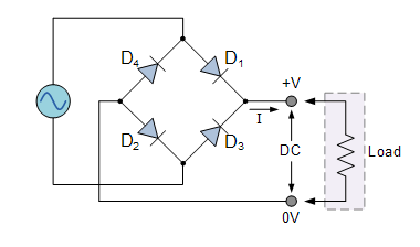
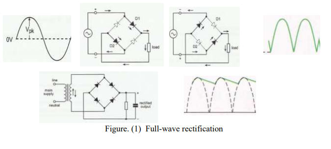
The conversion of alternating voltage (changes its direction) to directed voltage. This conversion is called rectification. To achieve the rectification of alternating voltage you must to use some circuit. The full-wave rectifier consists of four diodes, see Fig. 1. For a sinusoidal waveform the diodes D1 and D2 pass a current at first part 1 of waveform, because they are forward-biased. At the same time the diode D3 and D4 pass
a current for second part 2, because they are forward-biased. In this case the two halves of the input waveform (Full signal) passes through the bridge of diodes. The output voltage (rectified waveform) changes with time which makes it unstable with time. To produce a steady output directed voltage and free from variations the load resistor is connected in parallel with capacitor
Apparatus
1- Breadboard or Rastered socket panel, DIN A4.
2- Oscilloscope.
3- AC Power Supply (0-12V).
4- AC Voltmeter.
5- DC Voltmeter.
6- diode bridge or bridge rectifier.
7- Resistor 10kΩ.
8- 5 different capacitors (0.47µF, 4.7µF, 47µF, 100µF, 470µF).
9- Connecting wires.
10- Set of bridge plugs.
Procedure
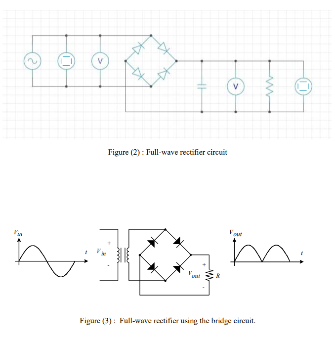
1- Connect the circuit as shown in figure (2), Do not connect the capacitor.
2- Keeping the input AC voltage at a certain value (Vin=5V).
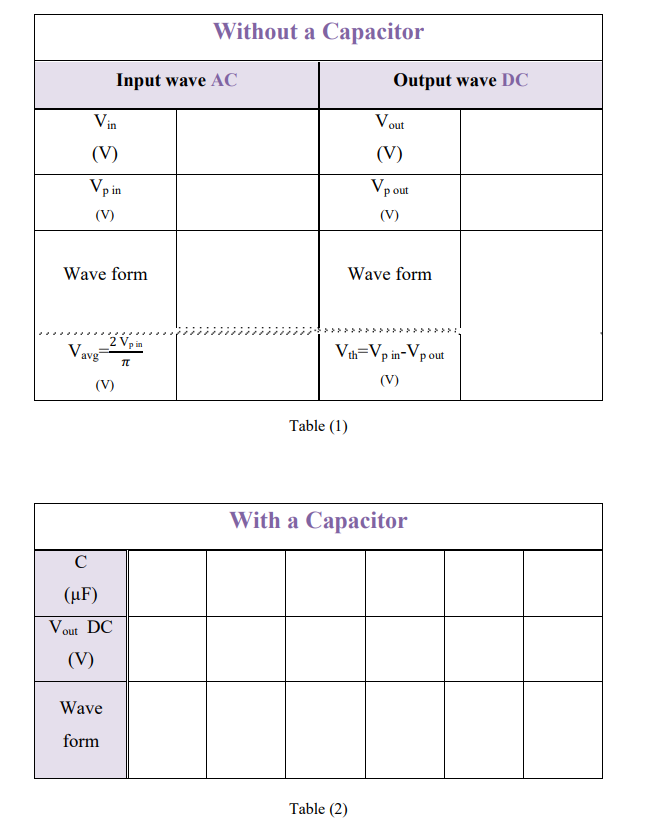
3- Determine the DC output voltage (Vout) of the rectifier circuit by DC Voltmeter.
4- Draw and label the parts of the input and the output wave form as viewed from the oscilloscope.
5- Add a one capacitor in the circuit and Determine in each time (Vout) and (output wave form).
6- Describe the viewed output wave form.
7- Determine the threshold voltage Vth and Vavg
Circuit Diagram
Data Sheet