

حيود الإلكتروناتElectron Diffraction
قِس قطري حلقتي الحيود D₁ وD₂ على شاشة الأنبوب عند كل جهد تسريع V. تحسب الأداة 1/√V ونصفي القطرين، ثم ميل كل خط والمسافتين d₁ وd₂ بين مستويات الجرافيت، مع عدم اليقين وخطوات الحل.Measure the diameters D₁ and D₂ of the two diffraction rings on the screen of the tube at each accelerating voltage V. The tool computes 1/√V and the radii, then the slope of each line and the lattice plane spacings d₁ and d₂ of graphite, with the uncertainty and the solution steps.
الهدف والأجهزةObjective and apparatus
- إظهار الخاصية الموجية للإلكترونات.
- تعيين المسافة بين المستويات البلورية في الجرافيت.
- To demonstrate the wave property of electrons.
- To determine the lattice plane spacing of graphite.
- أنبوب حيود الإلكترونات
- حامل الأنبوب
- مصدر جهد عالٍ
- قدمة ورنية دقيقة
- أسلاك توصيل
- Electron diffraction tube
- Tube stand
- High voltage power supply
- Precision vernier callipers
- Connection wires
الأساس النظريTheory
حيود الإلكترونات هو تداخل ينشأ من الطبيعة الموجية لحزمة إلكترونات تمر قرب المادة. فبحسب فرضية دي بروي (1924) لكل جسيم طول موجي يتناسب عكسياً مع زخمه، والإلكترونات السريعة أطوالها الموجية قصيرة تقارب رتبة المسافات بين الطبقات الذرية، فتحيد عند عبور طبقة رقيقة من مادة بلورية. وقد فسّر براغ الحزم الحائدة بانعكاس الموجات عن مستويات ذرية متوازية (الشكل 1).
Electron diffraction is the interference that arises from the wave nature of a beam of electrons passing near matter. According to the de Broglie hypothesis (1924) every particle has a wavelength inversely proportional to its momentum, and fast electrons have short wavelengths close to the order of the spacing between atomic layers, so they diffract on crossing a thin sheet of crystalline material. Bragg explained the diffracted beams through reflection of the waves from parallel planes of atoms (figure 1).
تظهر الحزم الحائدة حين تتداخل الانعكاسات من المستويات المتوازية تداخلاً بنّاءً، وذلك عند:
The diffracted beams appear when the reflections from parallel planes interfere constructively, which occurs when:
حيث λ الطول الموجي للإلكترونات، وθ زاوية براغ بين الحزمة والمستويات، وd المسافة بين المستويات في الجرافيت.
where λ is the wavelength of the electrons, θ the Bragg angle between the beam and the planes, and d the lattice plane spacing in graphite.
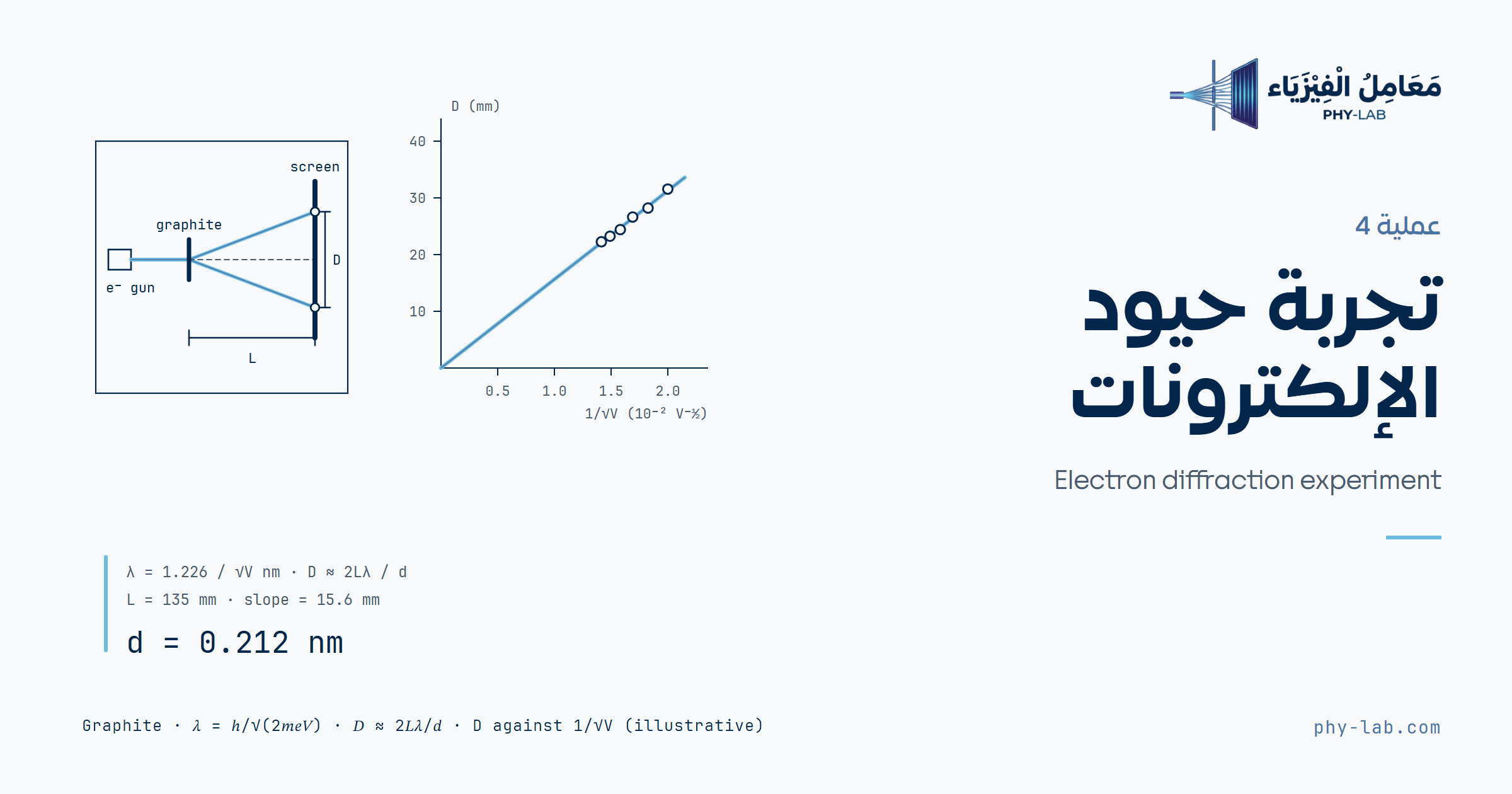
تنبعث الإلكترونات من كاثود ساخن، ويحدّها ثقب صغير، ثم تركّزها منظومة بصرية فتسقط حزمة ضيقة أحادية الطاقة على رقاقة جرافيت متعددة البلورات. والرقاقة بلّورات صغيرة كثيرة مرتبة عشوائياً، فيوجد دائماً بعضها في وضع يحقق شرط براغ، فتتكوّن على الشاشة المتفلورة حلقتان متحدتا المركز حول الحزمة غير الحائدة (الشكل 2).
The electrons are emitted by a hot cathode, a small beam is singled out by a pin diaphragm, and a focusing system then sends a narrow beam of one energy onto a polycrystalline graphite foil. The foil is a large number of small crystallites irregularly arranged, so some of them are always placed to meet the Bragg condition, and two rings concentric about the undiffracted beam appear on the fluorescent screen (figure 2).
من فرضية دي بروي:
From the de Broglie hypothesis:
وإذا تسارعت الإلكترونات خلال فرق جهد V اكتسبت طاقة حركية:
When the electrons are accelerated through a potential difference V they acquire the kinetic energy:
وبالتعويض عن h = 6.62 × 10⁻³⁴ J s وm = 9.11 × 10⁻³¹ kg وe = 1.6 × 10⁻¹⁹ C، وV بالفولت:
Substituting h = 6.62 × 10⁻³⁴ J s, m = 9.11 × 10⁻³¹ kg and e = 1.6 × 10⁻¹⁹ C, with V in volts:
ومن الشكل 4، إذا كان R نصف قطر الحلقة وL المسافة بين الرقاقة والشاشة:
From figure 4, if R is the radius of the ring and L the distance between the foil and the screen:
وللزوايا الصغيرة cos θ ≈ 1، فيكون:
For small angles cos θ ≈ 1, so that:
وبالتعويض عن λ وsin θ في قانون براغ عند n = 1:
Substituting λ and sin θ in Bragg’s law with n = 1:
وعند L = 13.5 cm:
With L = 13.5 cm:
فإذا رُسم R مقابل 1/√V كان الناتج خطاً مستقيماً يمر بالأصل، و:
So if R is plotted against 1/√V the result is a straight line through the origin, and:
والميل بوحدة m V^½ إذا كان R بالمتر، فتخرج d بالمتر. وللتحقق تحسب الأداة أيضاً d لكل قراءة دون تقريب، من المعادلتين (1) و(6) والطول الموجي بالتصحيح النسبي:
The slope is in m V^½ when R is in metres, so d comes out in metres. As a check the tool also computes d for each reading with no approximation, from equations (1) and (6) and the wavelength with the relativistic correction:
الشبيكة سداسية؛ إذا كان ثابتها a = 2.46 Å كان d₁ = (√3/2) a = 2.13 Å وd₂ = a/2 = 1.23 Å، فالنسبة d₁/d₂ = √3 = 1.732 لا تعتمد على L ولا V. والحلقة الأصغر تقابل المسافة الأكبر. أما المستويات الموازية لطبقات الجرافيت (3.35 Å) فلا تظهر عادة، لأن هذه الطبقات في الرقاقة تكون عمودية تقريباً على الحزمة فلا تحقق شرط براغ.
The lattice is hexagonal; with a constant a = 2.46 Å, d₁ = (√3/2) a = 2.13 Å and d₂ = a/2 = 1.23 Å, so the ratio d₁/d₂ = √3 = 1.732 does not depend on L or V. The smaller ring corresponds to the larger spacing. The planes parallel to the graphite layers (3.35 Å) do not usually show, because these layers in the foil lie nearly perpendicular to the beam and so do not meet the Bragg condition.
خطوات التجربةProcedure
الجهد يصل إلى 5 kV؛ لا تلمس الأسلاك والمصدر يعمل، ولا تغيّر التوصيل إلا بعد إطفائه. والأنبوب مفرّغ ورقيق الزجاج فلا تضغط عليه بالقدمة. ولا تترك البقعة المركزية ساطعة زمناً طويلاً حتى لا تتلف الشاشة.
The voltage reaches 5 kV; do not touch the wires while the supply is on, and change the wiring only after switching it off. The tube is evacuated and thin-walled, so do not press on it with the callipers. Do not leave the central spot bright for a long time, so that the screen is not damaged.
- جهّز الأجهزة كما في الشكل 5.
- صِل مقبسي تسخين الكاثود F₁ وF₂ بالمخرج الخلفي لمصدر الجهد العالي.
- صِل المقبسين C (غطاء الكاثود) وX (قطب التركيز) بالقطب السالب.
- صِل المقبس A (المصعد) بالقطب الموجب لمخرج 5 kV / 2 mA.
- أرّض القطب الموجب لمصدر الجهد العالي.
- طبّق جهد تسريع V < 5 kV ولاحظ نمط الحيود.
- غيّر الجهد من 2.5 kV إلى 4.5 kV بخطوات 0.5 kV، وقِس قطري الحلقتين D₁ وD₂ على الشاشة.
- لتعيين قطر الحلقة قِس حافتها الداخلية وحافتها الخارجية بالقدمة وخذ المتوسط.
- ارسم R₁ مقابل 1/√V.
- ارسم R₂ مقابل 1/√V.
- جِد ميل الخطين.
- جِد d₁ وd₂.
- Set up the apparatus as in figure 5.
- Connect the cathode heating sockets F₁ and F₂ to the output on the back of the high voltage supply.
- Connect the sockets C (cathode cap) and X (focusing electrode) to the negative pole.
- Connect the socket A (anode) to the positive pole of the 5 kV / 2 mA output.
- Ground the positive pole of the high voltage supply.
- Apply an accelerating voltage V < 5 kV and observe the diffraction pattern.
- Vary the voltage from 2.5 kV to 4.5 kV in steps of 0.5 kV and measure the diameters D₁ and D₂ of the rings on the screen.
- To find the diameter of a ring, measure its inner and outer edges with the callipers and take the average.
- Plot R₁ against 1/√V.
- Plot R₂ against 1/√V.
- Find the slopes of both lines.
- Find d₁ and d₂.
المحاكاة التفاعليةInteractive simulation
شغّل التسخين وارفع الجهد حتى تظهر الحلقتان. اختر الحلقة، وحرّك فكي القدمة حتى يقف الفك عند حافتها في المكبّر، ثم اضغط «حافة داخلية»، وكرر عند الحافة الخارجية. افعل ذلك للحلقتين، ثم اضغط «سجّل القراءة» فيُنقل متوسط كل حلقة إلى الجدول.
Switch the heater on and raise the voltage until the two rings appear. Choose the ring, move the jaws of the callipers until the jaw stands on its edge in the magnifier, then press “Inner edge”, and repeat at the outer edge. Do this for both rings, then press “Record reading” and the mean of each ring goes to the table.
النموذج: إلكترونات بطول موجي نسبي تحيد على مستويي الجرافيت وتصل إلى شاشة مسطحة على بعد L، وللحلقة عرض ثابت. الشاشة الفعلية منحنية. المحاكاة نموذج لا قياس.Model: electrons of relativistic wavelength diffract on the two graphite planes and reach a flat screen at the distance L, and each ring has a fixed width. The real screen is curved. The simulation is a model, not a measurement.
إدخال البياناتData entry
الجدول 1: أدخل V بالفولت والقطرين D₁ وD₂ بالمليمتر، وتُحسب الأعمدة الأخرى تلقائياً. يمكن ترك إحدى الحلقتين فارغة. وأضفنا خانة عدم يقين قراءة القطر δD، لأن حافة الحلقة ليست حادة.
Table 1: enter V in volts and the diameters D₁ and D₂ in millimetres; the other columns are computed automatically. One of the rings may be left empty. A field has been added for the uncertainty of a diameter reading δD, since the edge of a ring is not sharp.
| V (V) | 1/√V (V^−½) | D₁ (mm) | R₁ (mm) | D₂ (mm) | R₂ (mm) |
|---|
البيانات الحالية توضيحية من نموذج المحاكاة عند خمسة جهود من 2.5 kV إلى 4.5 kV؛ وليست قياساً.Current data are illustrative, from the simulation model at five voltages from 2.5 kV to 4.5 kV; not a measurement.
لصق بيانات أو تحميل ملف CSVPaste data or load a CSV file
سطر لكل جهد: V ثم D₁ ثم D₂، مثل 3000, 28.6, 49.8. ولترك D₁ فارغة اكتب 3000,,49.8.
One line per voltage: V then D₁ then D₂, such as 3000, 28.6, 49.8. To leave D₁ empty write 3000,,49.8.
النتائجResults
خطوات الحلSolution steps
التفسيرInterpretation


