Experiment:Using Manual and Digital Multimeter

Objective
To understand the operation and measurement techniques of both manual (analog) and digital multimeters in determining Voltage (V), Current (I), and Resistance (R).
Apparatus
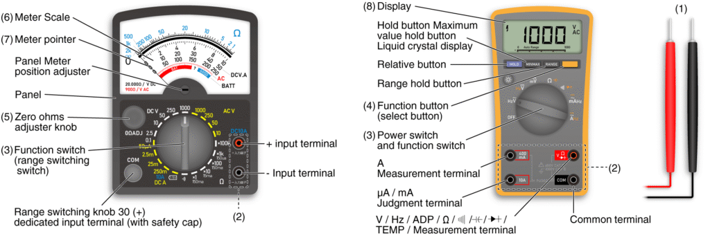
• Manual (Analog) Multimeter
• Digital Multimeter
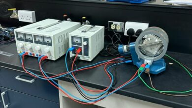
• DC Power Supply / Battery
• Resistors
• Connecting Wires
Theory
A multimeter is a multifunctional measuring instrument used to measure voltage, current, and resistance. Analog multimeters display readings via a moving needle, while digital ones show values on an LCD screen. Both follow Ohm’s Law: V = I × R.
Procedure
A. Measuring DC Voltage
1. Select DC voltage range (higher than expected).
2. Connect red lead to positive terminal and black to negative.
3. Place probes across the component.
4. Note the reading on the analog or digital display.
B. Measuring DC Current
1. Select appropriate DC current range.
2. Connect the meter in series with the circuit.
3. Read the current value (needle or digital display).
C. Measuring Resistance
1. Switch to Ω range.
2. For analog: short probes and set zero adjustment.
3. Measure resistance across the resistor.
4. Read from Ω scale or display.
Observation Table
| Unit | Digital Reading | Analog Reading | Range Selected | Measurement |
| Voltage (V) | ||||
| Current (I) | ||||
| Resistance (R) |
Calculations: R = V / I
Precautions
• Always start with the highest range.
• Observe correct polarity.
• Disconnect power before measuring resistance.
• Avoid parallax error with analog scale.
• Never connect current terminal directly across a voltage source.
Result
Both manual and digital multimeters were used successfully to measure voltage, current, and resistance. The results confirm Ohm’s Law within experimental limits.
Conclusion
This experiment demonstrates the differences in operation, accuracy, and ease of reading between analog and digital multimeters.