تعيين الطول الموجي لليزر بمعرفة معامل انكسار الهواء
Laser Wavelength from the Refractive Index of Air

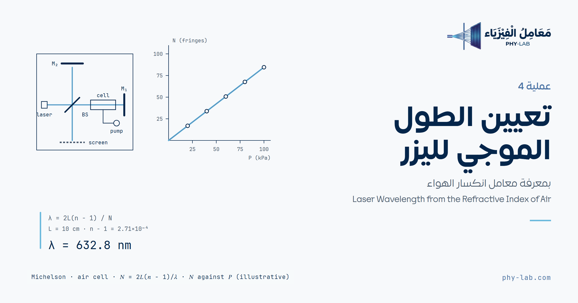
تعيين الطول الموجي لليزر بمعرفة معامل انكسار الهواءLaser Wavelength from the Refractive Index of Air
فرّغ خلية الهواء الموضوعة في أحد ذراعي مقياس مايكلسون وعُدّ الهدب z المارة، وتحسب الأداة معاملي الانكسار n وn′ من ميل n(P)، ثم λ = 2ℓ(n − n′)/z مع عدم اليقين وخطوات الحل.Evacuate the air cell placed in one arm of a Michelson interferometer and count the fringes z that pass, and the tool computes the refractive indices n and n′ from the slope of n(P), then λ = 2ℓ(n − n′)/z with the uncertainty and the solution steps.
الهدف والأجهزةObjective and apparatus
- تركيب مقياس تداخل مايكلسون.
- مشاهدة نمط التداخل أثناء تفريغ خلية موضوعة مسبقاً في مسار الشعاع.
- تعيين الطول الموجي لليزر.
- Assembling a Michelson interferometer.
- Observing the interference pattern while evacuating a chamber previously placed in the beam path.
- Determining the wavelength of a laser.
- ليزر هيليوم نيون وحامل الليزر
- لوح قاعدة البصريات وقواعد وحوامل
- مجزّئ الشعاع (لوح زجاجي نصف مفضض)
- عدسة كروية لتوسيع الشعاع، وآلية ضبط دقيق
- شاشة شبه شفافة، وقاعدة سرجية، ومسطرة
- خلية تفريغ وحاملها
- مضخة تفريغ يدوية بمقياس ضغط وصمام تنفيس
- He-Ne laser and laser support
- Laser optics base plate, optics bases and holders
- Beam divider (half-silvered glass plate)
- Spherical lens to spread the beam, and a fine adjustment mechanism
- Translucent screen, saddle base and ruler
- Vacuum cell and its component holder
- Hand vacuum pump with pressure gauge and relief valve
الأساس النظريTheory
في مقياس التداخل يسقط شعاع ليزر الهيليوم نيون على لوح زجاجي نصف مفضض بزاوية 45°، فينقسم: جزء يذهب إلى المرآة M1 في نهاية الذراع الجانبي وينعكس عائداً إلى الشاشة، والجزء الآخر ينفذ عبر اللوح ثم عبر الخلية إلى المرآة M2، وينعكس عائداً عبر الخلية إلى اللوح ومنه إلى الشاشة (الشكل 1).
In the interferometer the He-Ne laser beam falls on a half-silvered glass plate at 45° and splits: one part goes to mirror M1 at the end of the side arm and is reflected back to the screen, and the other passes through the plate and then through the cell to mirror M2, and is reflected back through the cell to the plate and on to the screen (figure 1).
يتداخل الشعاعان على الشاشة فيظهر نمط من حلقات مضيئة ومعتمة متحدة المركز (وقد تتشوه الحلقات بسبب عيوب المرايا). في المناطق المضيئة تصل قمم موجتي الشعاعين معاً، وفي المعتمة تصل قمة إحداهما مع قاع الأخرى. إذا تغير طول المسار البصري لأحد الشعاعين بطول موجي واحد انزاح النمط هدبة واحدة. طول المسار البصري nℓ، حيث n معامل الانكسار وℓ طول المسار الهندسي، فالتغير في المسار البصري بين وجود الهواء في الخلية وتفريغه تماماً:
The two beams interfere on the screen, giving a pattern of concentric bright and dark rings (the rings may be distorted by imperfections of the mirrors). In the bright regions the crests of the two waves arrive together, and in the dark ones the crest of one arrives with the trough of the other. If the optical path length of one beam changes by one wavelength, the pattern shifts by one fringe. The optical path length is nℓ, where n is the refractive index and ℓ the physical path length, so the change in optical path between air in the cell and the cell fully evacuated is:
وℓ هنا المسافة بين نافذتي الخلية. يعبر الضوء الخلية مرتين (ذهاباً وإياباً)، فإذا مرّت z هدبة كان تغير المسار الكلي 2Δd = zλ:
Here ℓ is the distance between the windows of the cell. The light crosses the cell twice (there and back), so if z fringes pass, the total path change is 2Δd = zλ:
لا تُفرَّغ الخلية تماماً، بل يُخفض ضغطها إلى P′ (نحو 30 kPa). ومعامل انكسار الغاز يزيد خطياً مع ضغطه (الشكل 3)، بميل يعطيه الدليل للهواء عند درجة حرارة الغرفة:
The cell is not fully evacuated; its pressure is lowered to P′ (about 30 kPa). The refractive index of a gas increases linearly with its pressure (figure 3), with a slope given by the manual for air at room temperature:
فإذا بدأ التفريغ من ضغط الغرفة P₀ وانتهى عند P′ كان n = 1 + kP₀ وn′ = 1 + kP′، والطول الموجي:
So if the pumping starts at the room pressure P₀ and ends at P′, then n = 1 + kP₀ and n′ = 1 + kP′, and the wavelength is:
يفترض الدليل أن ضغط الغرفة 100 kPa فيأخذ n = 1.000272. المهم في المعادلة (5) فرق الضغط P₀ − P′ الذي فُرّغ فعلاً؛ والضغط الجوي في المدن المرتفعة أقل (نحو 94 kPa في الرياض)، فأدخل ضغط معملك. والميل k يتناسب عكسياً مع درجة الحرارة المطلقة.
The manual assumes a room pressure of 100 kPa and so takes n = 1.000272. What matters in equation (5) is the pressure difference P₀ − P′ actually pumped out; the atmospheric pressure in high cities is lower (about 94 kPa in Riyadh), so enter your lab pressure. The slope k is inversely proportional to the absolute temperature.
خطوات التجربةProcedure
ضبط الجهازAlignment
- شغّل الليزر وانظر إلى شاشة المشاهدة. إذا رأيت نمط الحلقات ويتغير بتدوير الميكرومتر فالجهاز مضبوط، ويمكنك تجاوز خطوات الضبط الباقية.
- انزع العدسة من حامل المكوّن المجاور لليزر.
- انزع مرآة مجزّئ الشعاع بالمفك، وشغّل الليزر، واضبط موضعه ليتجه الشعاع مباشرة إلى مركز المرآة M2، بحيث ينعكس الشعاع عائداً إلى الليزر نفسه.
- أعد مرآة مجزّئ الشعاع وانظر إلى الشاشة؛ قد ترى مجموعتين من البقع الصغيرة، واحدة من كل مرآة، في كل منهما بقعة ساطعة وأخرى أقل سطوعاً ناتجة عن الانعكاسات المتعددة.
- استعمل براغي الضبط في المرآة M1 (القابلة للإمالة) لتنطبق البقعتان الساطعتان؛ وعند انطباقهما ستتلألآن بسبب تداخل الشعاعين.
- أخيراً أعد العدسة، وحرّكها حتى ترى نمط الحلقات على الشاشة.
- Turn on the laser and look at the observation screen. If you see the ring pattern and it changes when you turn the micrometer screw, the apparatus is aligned and you may skip the remaining alignment steps.
- Take out the lens from the component holder next to the laser.
- Remove the beam-splitter mirror with a screwdriver, turn on the laser and adjust its position to direct the beam straight into the centre of mirror M2, so that the beam is reflected right back into the laser.
- Restore the beam-splitter mirror and look at the screen; you may see two sets of small spots, one from each mirror, each with a bright spot and several less-bright ones produced by multiple reflections.
- Use the adjusting screws of mirror M1 (the tilt mirror) to make the bright spots overlap; as they overlap they will twinkle because of the interference of the two beams.
- Finally, restore the lens and slide it around until you see the ring pattern on the screen.
القياسMeasurement
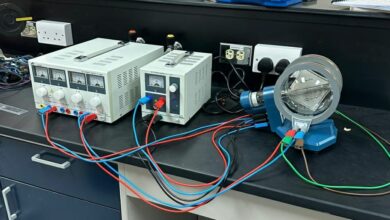
- ثبّت خلية الهواء أمام المرآة M2 كما في الشكل 2، وصِلها بمضخة التفريغ اليدوية بالأنبوب.
- فرّغ الخلية من الهواء ببطء، وعُدّ انتقالات الهدب أثناء ذلك. يكفي خفض الضغط إلى نحو 30 kPa.
- كرّر الخطوة السابقة عشر مرات، وسجّل قيمة z في الجدول 1.
- أوجد متوسط z.
- سجّل قيمة ℓ.
- احسب الطول الموجي من المعادلة (5): λ = 2ℓ(n − n′)/z، حيث n = 1.000272 معامل انكسار الهواء عند 100 kPa، وn′ معامل الانكسار عند 30 kPa: n′ = 1 + 30 kPa × k.
- Mount the air cell in front of mirror M2, as shown in figure 2, and connect it to the hand vacuum pump with the tubing.
- Slowly pump the air out of the cell, counting the number of fringe transitions as this is done. It is sufficient to reduce the pressure to about 30 kPa.
- Repeat the previous step ten times and record the value of z in table 1.
- Find the average value of z.
- Record the value of ℓ.
- Calculate the wavelength from equation (5): λ = 2ℓ(n − n′)/z, where n = 1.000272 is the refractive index of air at 100 kPa and n′ is the refractive index at 30 kPa: n′ = 1 + 30 kPa × k.
فرّغ ببطء ليتمكن العدّ من متابعة الهدب، وابدأ كل محاولة من ضغط الغرفة (افتح صمام التنفيس ثم أغلقه)، وانتهِ عند الضغط نفسه P′ في كل المحاولات.
Pump slowly so the count can follow the fringes, start every trial from the room pressure (open the relief valve, then close it), and stop at the same pressure P′ in all trials.
المحاكاة التفاعليةInteractive simulation
اضغط «ابدأ العدّ» والخلية عند ضغط الغرفة، ثم اضغط المضخة مرة بعد مرة وراقب الهدب تتحرك على الشاشة حتى يصل الضغط إلى نحو 30 kPa (اضبطه بالتنفيس الخفيف)، ثم «سجّل z». افتح صمام التنفيس لإرجاع الهواء قبل المحاولة التالية. الطول الموجي في المحاكاة غير معروض، والمطلوب تعيينه.
Press “Start count” with the cell at room pressure, then press the pump stroke after stroke and watch the fringes move on the screen until the pressure reaches about 30 kPa (adjust it with a slight release), then “Record z”. Open the relief valve to let the air back before the next trial. The wavelength in the simulation is not shown; finding it is the task.
النموذج: مقياس مايكلسون وفي ذراعه خلية طولها 3.00 cm، ومعامل انكسار الهواء فيها n = 1 + kP؛ كل ضغطة مضخة تسحب جزءاً من الهواء المتبقي، ودرجة الحرارة تزيح النمط قليلاً بين المحاولات، فقد يختلف z بهدبة. الضغط الجوي في المعمل المحاكى 94.0 kPa. المحاكاة نموذج لا قياس.Model: a Michelson interferometer with a 3.00 cm cell in one arm, where the refractive index of air is n = 1 + kP; each pump stroke removes part of the remaining air, and the temperature shifts the pattern slightly between trials, so z may differ by one fringe. The atmospheric pressure in the simulated lab is 94.0 kPa. The simulation is a model, not a measurement.
إدخال البياناتData entry
الجدول 1: عدد الهدب z في كل محاولة، ويُحسب المتوسط في آخر الجدول. القيمتان 100 و30 kPa هما ما يفترضه الدليل؛ عدّلهما إلى ضغط معملك وضغط النهاية الفعلي.
Table 1: the number of fringes z in each trial, with the average at the bottom of the table. The values 100 and 30 kPa are what the manual assumes; change them to your lab pressure and the actual end pressure.
| رقمNo. | z |
|---|---|
| المتوسطAverage value |
البيانات الحالية توضيحية من نموذج المحاكاة: خلية 3.00 cm، وتفريغ من 94.0 إلى 30.0 kPa، وz عدد صحيح يختلف بهدبة بين المحاولات؛ وليست قياساً.Current data are illustrative, from the simulation model: a 3.00 cm cell, pumped from 94.0 to 30.0 kPa, and z a whole number that differs by one fringe between trials; not a measurement.
لصق بيانات أو تحميل ملف CSVPaste data or load a CSV file
النتائجResults
خطوات الحلSolution steps
التفسيرInterpretation