Objectives

The resistivity and Hall voltage of a rectangular germanium sample are measured as a function of temperature and magnetic field. The band gab, the specific conductivity, the type of charge carrier , the mobility of the charge carriers and the charge-carrier concentration p are related through the Hall constant RH are determined from the measurements.
Apparatus
1- Hall Effect Module.
2-Hall Effect, P-Ge, Carrier Board.
3- 2 Coil, 600 Turns.
4- Iron Core, U-Shaped.
5- 1 Pair, Pole Pieces, Plane, 30 X 30 X 48 mm.
6- Hall Probe, Tangential, With Protective Cap.
7- Power Supply 0-12 V DC/ 6 V, 12 V AC.
8- Tripod Base.
9- Support Rod , Square, L = 250 mm.
10- Right Angle Clamp.
11- Connecting Cables.
12-Digital Teslameter.
13- Digital Multimeter
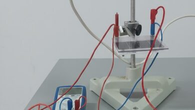
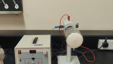
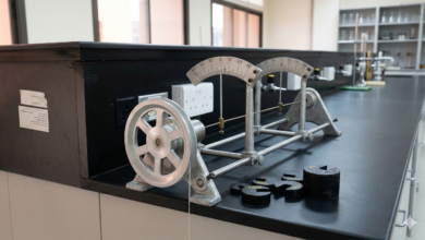
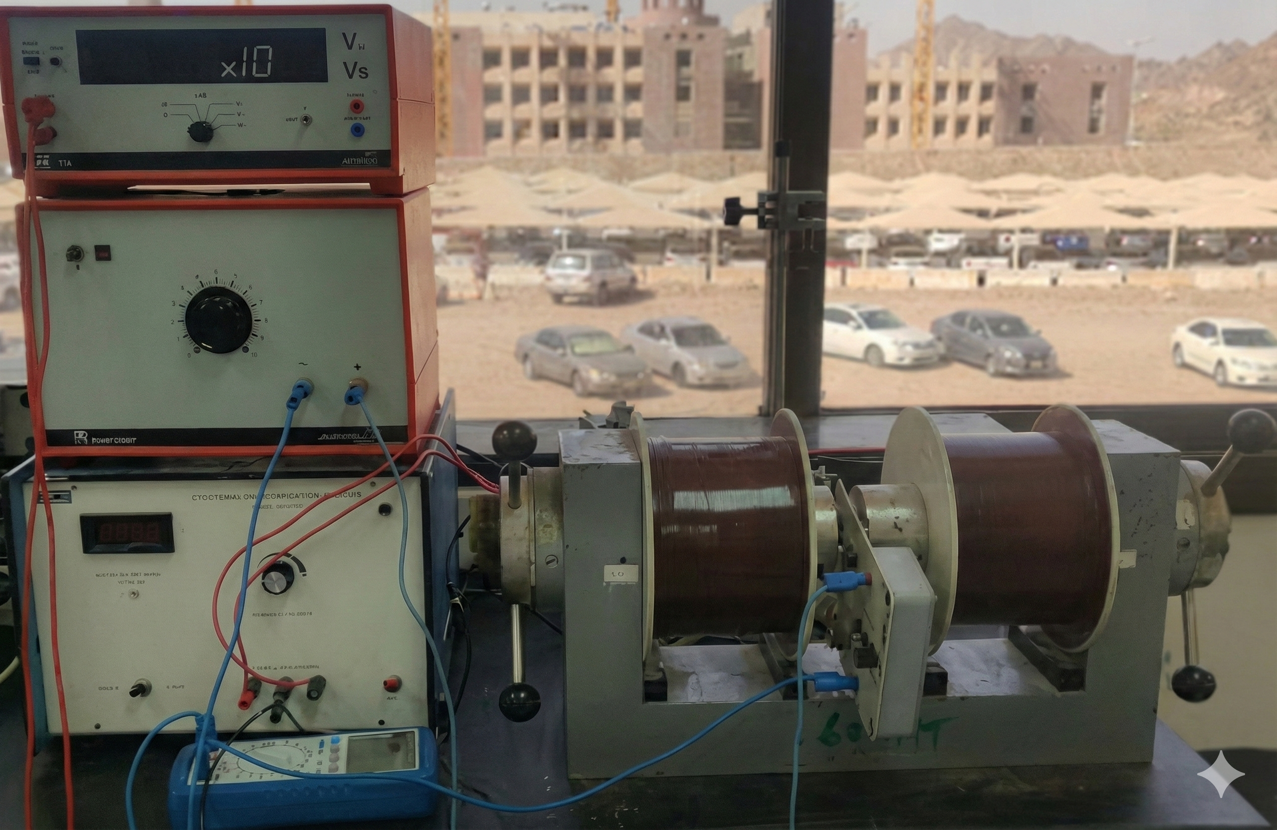
Set-up
The experimental set-up is shown in Fig.1. The test piece on the board has to be put into the hall-effect-module via the guide-groove. The module is directly connected with the 12 V~ output of the power unit over the AC-input on the backside of the module.
The plate has to be brought up to the magnet very carefully, so as not to damage the crystal in particular, avoid bending the plate. The Hall voltage and the voltage across the sample are measured with a multimeter. Therefore, use the sockets on the front-side of the module. The current and temperature can be easily read on the integrated display of the module
The magnetic field has to be measured with the teslameter via a hall probe, which can be directly put in-to the groove in the module as shown in Fig. 1. So you can be sure that the magnetic flux is measured directly on the Ge-sample.
Steps to conduct the experiment
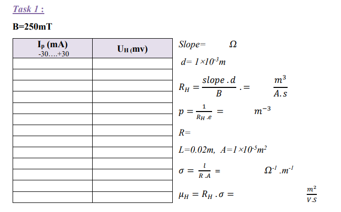
Task 1
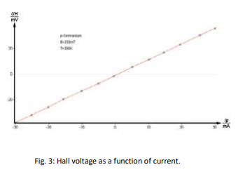
The Hall voltage is measured at room temperature and constant magnetic field as a function of the control current and plotted on a graph (measurement without compensation for defect voltage).
1-Set the magnetic field to a value of 250 mT by changing the voltage and current on the power supply.
2-Connect the multimeter to the sockets of the hall voltage (UH) on the front-side of the module.
3- Set the display on the module into the ”current-mode”.
4-Determine the hall voltage as a function of the current from -30 mA up to 30 mA in steps of nearly 5mA.
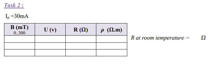
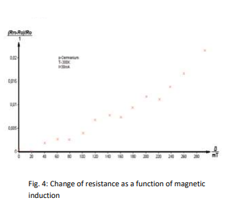
Task 2
The voltage across the sample is measured at room temperature and constant control current as a function of the magnetic induction B.
1-Set the control current to 30 mA.
2-Connect the multimeter to the sockets of the sample voltage on the front-side of the module.
3-Determine the sample voltage as a function of the positive magnetic induction B up to 300 mT.
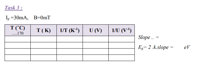
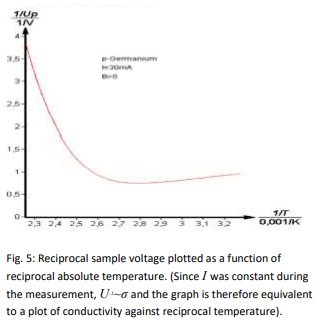
Task 3
The voltage across the sample is measured at constant control current as a function of the temperature. The band spacing of germanium is calculated from the measurements.
1-Be sure, that the display works in the temperature mode during the measurement.
2-At the beginning, set the current to a value of 30 mA.
3-The magnetic field is off.
4-The current remains nearly constant during the measurement, but the voltage changes according to a change in temperature.
5-Set the display in the temperature mode, now. Start the measurement by activating the heating coil with the ”on/off”-knob on the backside of the module.
6-Determine the change in voltage dependent on the change in temperature for a temperature range of room temperature to a maximum of 140°C
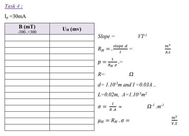
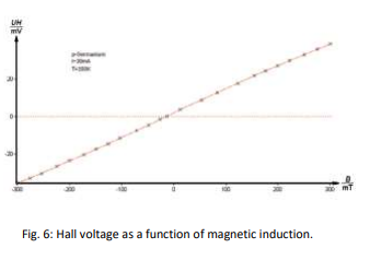
Task 4
The Hall voltage UH is measured as a function of the magnetic induction B, at room temperature. The sign of the charge carriers and the Hall constant RH together with the Hall mobility μH and the carrier concentration p are calculated from the measurements.
1-Set the current to a value of 30 mA.
2-Connect the multimeter to the sockets of the hall voltage (UH) on the front-side of the module.
3-Determine the Hall voltage as a function of the magnetic induction.
4-Start with -300 mT by changing the polarity of the coil-current and increase the magnetic induction in steps of nearly 20 mT. At zero point, you have to change the polarity
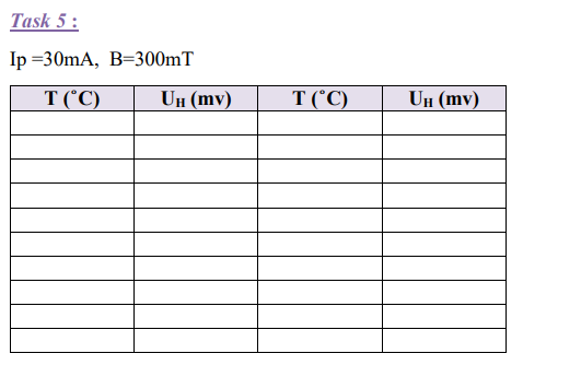
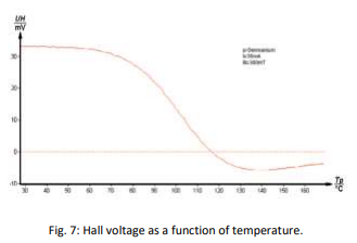
Task 5
The Hall voltage UH is measured as a function of temperature at constant magnetic induction B and the values are plotted on a graph.
1-Set the current to 30 mA and the magnetic induction to 300 mT.
2-Determine the Hall voltage as a function of the temperature.
3-Set the display in the temperature mode.
4-Start the measurement by activating the heating coil with the ”on/off”- knob on the backside of the module.