Determining the capacitance of a plate capacitor –Measuring the charge with the electrometer amplifier

Experiment Objectives
Measuring the charge Q on a plate capacitor as a function of the applied voltage U.
Determining the capacitance C as a function of the area A of the plates.
Determining the capacitance C with different dielectrics between the plates.
Determining the capacitance C as function of the distance d between the plates.
Principles
The simplest design of a capacitor is the parallel-plate capacitor. Its capacitance depends on the charge, the applied voltage, the plate area, the distance between the plates, and the dielectric material placed between them.
1. Definition of Capacitance
Equation: 1 C = Q / U
Q: charge on the capacitor U: applied voltage
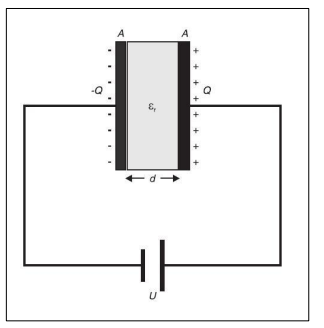
2. Capacitance of a Parallel-Plate Capacitor
Equation:2 C = ε0 · εr · A / d
ε0: permittivity of free space εr: relative permittivity of the dielectric A: plate area d: distance between plates
This formula is valid when the plate separation is much smaller than their dimensions and the electric field can be considered uniform.
3. Proportionality With Plate Area
Equation: 3 C ∝ A
The capacitance increases in proportion to the plate area.
4. Proportionality With Inverse Distance
Equation:4 C ∝ 1 / d
The capacitance decreases when the distance between the plates increases.
5. Charge Measurement Using Electrometer Amplifier
Equation: 5 Q = CA · UA
CA: reference capacitor connected to the electrometer amplifier UA: output voltage of the amplifier
This equation relates the measured charge to the reference capacitor and the output voltage of the electrometer amplifier.
Apparatus
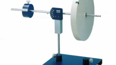
1 Demountable capacitor…………………………….544 23
1 Power supply 450 V…………………………………522 27
1 Electrometer amplifier……………………………… 532 14
1 Capacitor 10 nF, STE 2/19 ………………………. 578 10
1 Capacitor 0.1 µF, STE 2/19 ……………………… 578 31
1 Connecting rod ………………………………………. 532 16
2 Multimeter LDanalog 20……………………………531 120
1 Two-way switch ……………………………………… 504 48
4 Connecting lead 19 A, 50 cm, red/blue, pair..501 45
2 Connecting lead 19 A, 100 cm, red/blue, pair 501 46
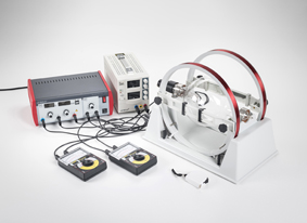
Setup
The experimental setup is illustrated in Fig. 1.
Mount the pair of small plates (A = 400 cm2), and set the distance d between the plates to 4 mm with the spacers.
connect the negative pole of the power supply 450 V to the right plate and to the earth of the electrometer amplifier. Connect the connection rod to the earth as well.
Connect the positive pole of the power supply 450 V to socket B of the two-way switch.
Connect socket A of the two-way switch to the left plate and socket C to the input of the electrometer amplifier
Plug the reference capacitor CA = 10 nF in at the electrometer amplifier, and connect the voltmeter to the output.
Connect the other voltmeter to the power supply 450 V for measuring the voltage U.

Carrying out the Experiment
Carrying Out the Experiment
a) Measuring the Charge as a Function of Voltage for Different Plate Areas
- Switch to connection AC, discharge the capacitor using the grounding rod, and check the zero reading of the electrometer.
- Hold the grounding rod, switch to connection AB, and set the power supply output voltage to 50 V.
- Switch back to AC, measure the charge Q using the electrometer amplifier, and record the value.
- Repeat the measurement for several voltages.
- Replace the small plates with the larger plates (A = 800 cm², d = 4 mm).
- Switch to connection AC again and discharge the capacitor.
- Hold the grounding rod and record a second series of Q–U measurements.
b) Measuring the Charge for Different Dielectrics
- Place the polystyrene sheet between the large plates, ensuring full surface contact.
- Switch to AC and discharge the capacitor.
- Hold the grounding rod and measure the charge Q for different voltages.
- Replace the reference capacitor with CA = 100 nF on the electrometer amplifier.
- Replace the polystyrene sheet with a glass sheet, discharge again, and repeat the Q–U measurements.
c) Determining the Capacitance as a Function of Plate Distance
- Set the supply voltage to 300 V.
- Remove the dielectric and set the plate separation to 6 mm.
- Switch to AC and discharge the capacitor using the grounding rod.
- Hold the grounding rod, switch to AB to charge the capacitor, then back to AC to measure the charge Q.
- Record the charge Q for each distance.
- Reduce the distance sequentially to 4 mm, 3 mm, 2 mm, and 1 mm, repeating the charge measurement each time.
Measurement Example
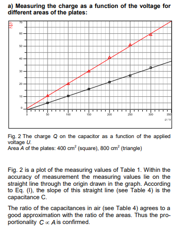
a) Measuring the charge as a function of the voltage for different areas of the plates:
Table 1: the charge Q recorded as a function of the applied voltage U with different areas A of the plates
| Q A=800cm | Q A=400cm | v |
| 50 | ||
| 100 | ||
| 150 | ||
| 200 | ||
| 250 | ||
| 300 |
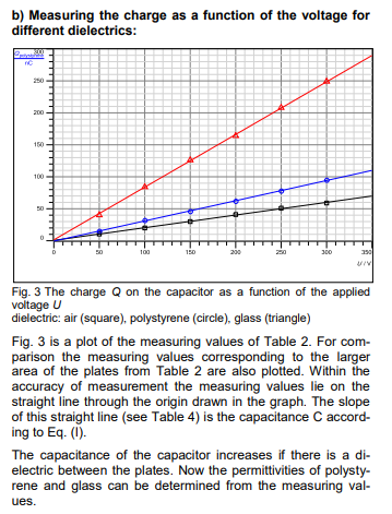
b) Measuring the charge as a function of the voltage for different dielectrics:
Table 2: The charge Q recorded as a function of the applied voltage U for different dielectrics(A= 800 cm2)
| Q glass | Q polystyrene | v |
| 50 | ||
| 100 | ||
| 150 | ||
| 200 | ||
| 250 | ||
| 300 |
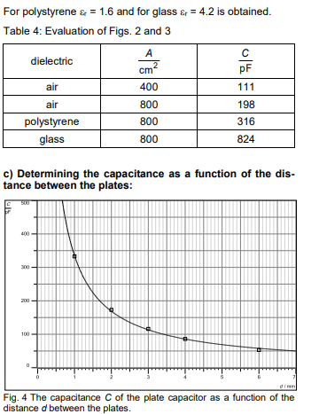
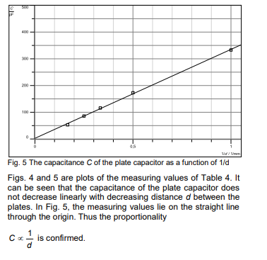
c) Determining the capacitance as a function of the distance between the plates:
Table 3: The charge Q (at U = 300 V) and the capacitance C as functions of the distance d between the plates
| C pF | Q nAs | d mm |
| 1 | ||
| 2 | ||
| 3 | ||
| 4 | ||
| 5 | ||
| 6 |
Evaluation and results