تعيين الطول الموجي لليزر الهيليوم نيون بمقياس تداخل مايكلسون
He-Ne Laser Wavelength with a Michelson Interferometer

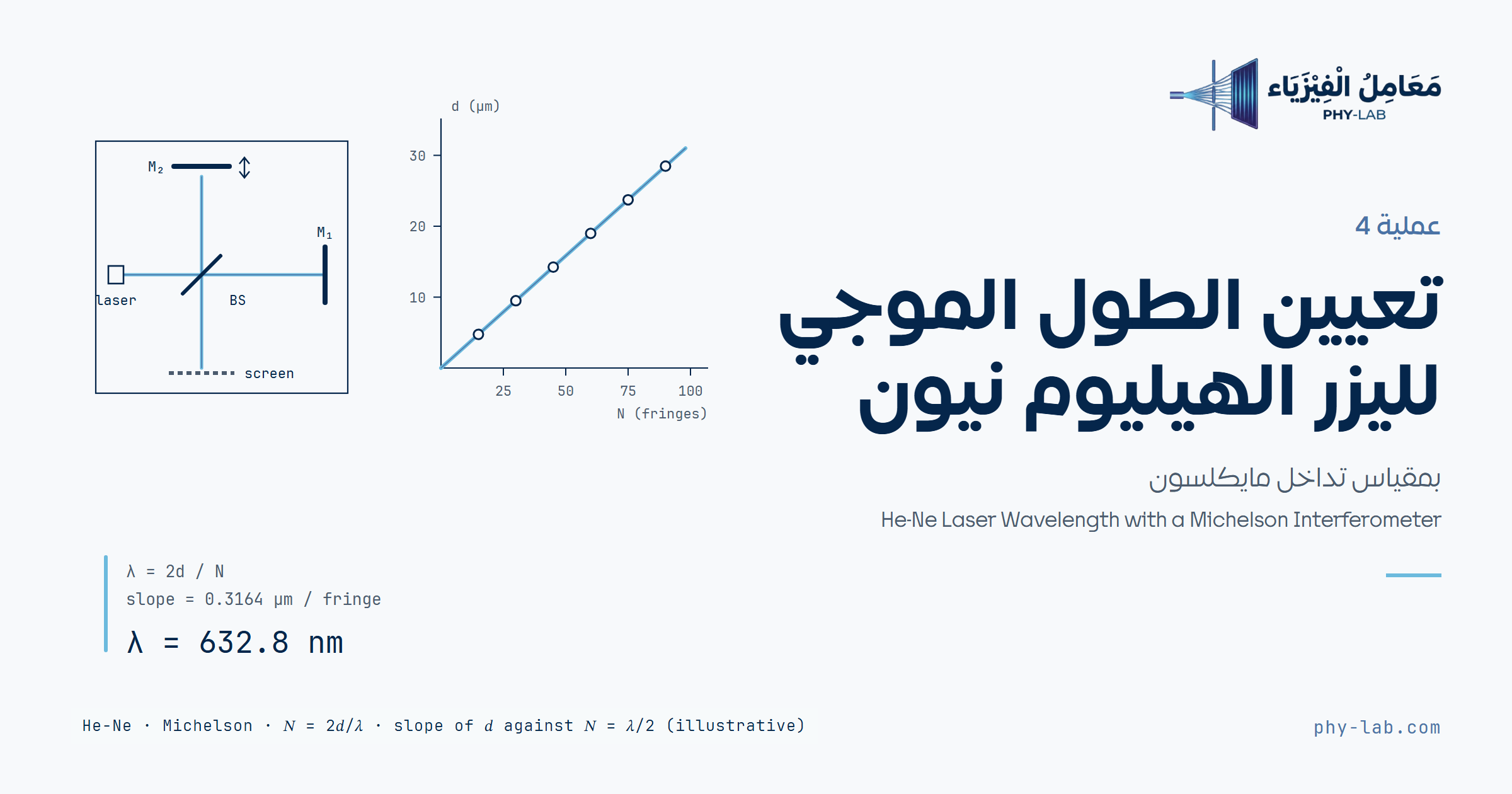
تعيين الطول الموجي لليزر الهيليوم نيون بمقياس تداخل مايكلسونHe-Ne Laser Wavelength with a Michelson Interferometer
أدِر ميكرومتر المرآة المتحركة وعُدّ الهدب N المارة بنقطة على الشاشة، وسجّل إزاحة المرآة d، وتحسب الأداة λ = 2d/N لكل محاولة ومتوسطها وميل d مقابل N مع عدم اليقين وخطوات الحل.Turn the micrometer of the movable mirror, count the fringes N passing a point on the screen and record the mirror displacement d, and the tool computes λ = 2d/N for each trial, their average and the slope of d against N, with the uncertainty and the solution steps.
الهدف والأجهزةObjective and apparatus
- تركيب مقياس تداخل مايكلسون.
- مشاهدة نمط التداخل.
- تعيين الطول الموجي لليزر الهيليوم نيون.
- Assembling a Michelson interferometer.
- Observing the interference pattern.
- Determining the wavelength of a He-Ne laser.
- ليزر هيليوم نيون وحامل الليزر
- لوح قاعدة البصريات وقواعد وحوامل
- مجزّئ الشعاع (مرآة نصف مفضضة)
- مرآة ثابتة قابلة للضبط (المرآة 1) ومرآة متحركة (المرآة 2)
- آلية ضبط دقيق بميكرومتر (كل تدريجة 1 µm من حركة المرآة)
- عدسة كروية قصيرة البعد البؤري لتوسيع الشعاع
- شاشة شبه شفافة، وقاعدة سرجية، ومسطرة
- He-Ne laser and laser support
- Laser optics base plate, optics bases and holders
- Beam divider (half-silvered mirror)
- Adjustable fixed mirror (mirror 1) and movable mirror (mirror 2)
- Fine adjustment mechanism with a micrometer (each tick is 1 µm of mirror motion)
- Short focal length spherical lens to spread the beam
- Translucent screen, saddle base and ruler
الأساس النظريTheory
فكرة مقياس مايكلسون أن يُقسم شعاع ضوئي إلى شعاعين، ويُؤخَّر أحدهما بالنسبة للآخر، ثم يُجمعان ليتداخلا. يسقط ضوء أحادي اللون على مرآة نصف مفضضة (طبقة معدنية رقيقة جداً)، فينعكس نحو نصف الشدة إلى المرآة 1 وينفذ النصف الآخر إلى المرآة 2. ترجع الأشعة المنعكسة عن المرآتين إلى المرآة نصف المفضضة، ويتجه نصف شدة كل منهما إلى الشاشة (الشكل 1).
The idea of the Michelson interferometer is to split a beam of light into two beams, delay one with respect to the other, and then recombine them to interfere. Monochromatic light falls on a half-silvered mirror (a very thin metallic coating), so about half the intensity is reflected to mirror 1 and half is transmitted to mirror 2. The light reflected by the two mirrors returns to the half-silvered mirror, and half the intensity of each beam goes to the screen (figure 1).
إذا كان المصدر نقطياً فلكل شعاع صورة للمصدر خلف المرآتين. إذا تساوى بعدا المرآتين عن المرآة نصف المفضضة انطبقت الصورتان، أما إذا كانت المرآة 2 أقرب بمسافة d فتصبح صورتها أقرب بمسافة 2d؛ فيرى الراصد مصدرين نقطيين بينهما 2d يتداخل ضوؤهما، ويكون التداخل بنّاءً في المركز إذا كان:
If the source is a point source, each beam forms an image of it behind the mirrors. If the two mirrors are at equal distances from the half-silvered mirror the two images coincide, but if mirror 2 is closer by a distance d its image becomes closer by 2d; the observer then sees two point sources 2d apart whose light interferes, and the interference at the centre is constructive if:
والضوء الذي يصل الشاشة بزاوية θ عن المحور يقطع فرق مسار 2d cos θ، فيظهر على الشاشة نمط من حلقات مضيئة ومعتمة متحدة المركز (الهدب)، شرط الحلقة المضيئة فيه:
Light reaching the screen at an angle θ from the axis has a path difference 2d cos θ, so the screen shows a pattern of concentric bright and dark rings (fringes), with the bright-ring condition:
حين تتحرك المرآة 2 مسافة d يتغير فرق المسار بمقدار 2d، وكلما تغير بمقدار λ مرّت هدبة واحدة بنقطة ثابتة (وتولد حلقة من المركز أو تختفي فيه). فإذا مرّت N هدبة:
When mirror 2 moves a distance d the path difference changes by 2d, and every change of λ makes one fringe pass a fixed point (a ring is born at the centre or vanishes into it). So if N fringes pass:
يُحسب λ لكل محاولة ثم المتوسط وخطؤه المعياري. والأدق أن تُرسم d مقابل N: خط مستقيم ميله λ/2، ومقطعه d₀ يكشف الخطأ الثابت في القراءة (مثل الارتداد في الميكرومتر):
λ is computed for each trial, then the average and its standard error. More precisely, d is plotted against N: a straight line of slope λ/2, whose intercept d₀ reveals a constant reading error (such as micrometer backlash):
الطول الموجي المعروف لليزر الهيليوم نيون الأحمر λ = 632.8 nm. كل تدريجة في الميكرومتر 1 µm = 1000 nm من حركة المرآة، فإزاحة 3.2 تدريجة هي d = 3200 nm.
The known wavelength of the red He-Ne laser is λ = 632.8 nm. Each micrometer tick is 1 µm = 1000 nm of mirror motion, so a displacement of 3.2 ticks is d = 3200 nm.
خطوات التجربةProcedure
ضبط الجهازAlignment
- شغّل الليزر وانظر إلى شاشة المشاهدة. إذا رأيت نمط الحلقات ويتغير بتدوير الميكرومتر فالجهاز مضبوط، ويمكنك تجاوز بقية خطوات الضبط.
- انزع العدسة من حامل المكوّن المجاور لليزر.
- انزع مرآة مجزّئ الشعاع بالمفك، وشغّل الليزر، واضبط موضعه ليتجه الشعاع مباشرة إلى مركز المرآة المتحركة (المرآة 2)، بحيث ينعكس الشعاع عائداً إلى الليزر نفسه.
- أعد مرآة مجزّئ الشعاع وانظر إلى الشاشة؛ قد ترى مجموعتين من البقع الصغيرة، واحدة من كل مرآة، في كل منهما بقعة ساطعة وأخرى أقل سطوعاً ناتجة عن الانعكاسات المتعددة.
- استعمل براغي الضبط في المرآة الثابتة (المرآة 1) لتنطبق البقعتان الساطعتان؛ وعند انطباقهما ستتلألآن بسبب تداخل الشعاعين.
- أخيراً أعد العدسة، وحرّكها حتى ترى نمط الحلقات على الشاشة.
- Turn on the laser and look at the observation screen. If you see the ring pattern and it changes when you turn the micrometer screw, the apparatus is aligned and you may skip the remaining alignment steps.
- Take out the lens from the component holder next to the laser.
- Remove the beam-splitter mirror with a screwdriver, turn on the laser and adjust its position to direct the beam straight into the centre of the movable mirror (mirror 2), so that the beam is reflected right back into the laser.
- Restore the beam-splitter mirror and look at the screen; you may see two sets of small spots, one from each mirror, each with a bright spot and several less-bright ones produced by multiple reflections.
- Use the adjusting screws of the fixed mirror (mirror 1) to make the bright spots overlap; as they overlap they will twinkle because of the interference of the two beams.
- Finally, restore the lens and slide it around until you see the ring pattern on the screen.
قياس الطول الموجيMeasuring the wavelength
- أدِر الميكرومتر في اتجاه واحد (مع عقارب الساعة أو عكسها) نحو لفة كاملة، ثم استمر في الاتجاه نفسه حتى تمر N هدبة بنقطة على الشاشة. سجّل عدد التدريجات المقابلة لهذه الهدب (كل تدريجة 1 µm)؛ فهي d في المعادلة (3)، ثم احسب λ = 2d/N.
- كرّر الخطوة 7 وقِس المسافة d اللازمة لمرور N هدبة أخرى بالنقطة نفسها، وسجّل البيانات في الجدول 1.
- عيّن متوسط الطول الموجي.
- Turn the micrometer in one direction (clockwise or anticlockwise) for about one rotation, then keep turning in the same direction until N fringes pass a point on the screen. Record the number of ticks corresponding to these fringes (each tick is 1 µm); this is d in equation (3), then compute λ = 2d/N.
- Repeat step 7 and measure the distance d needed for another N fringes to pass the same point, and record the data in table 1.
- Determine the average wavelength.
اللفة الأولى في الخطوة 7 تزيل الارتداد (الفراغ في لولب الميكرومتر)؛ فلا تعكس اتجاه الدوران أثناء العدّ. اختر نقطة مرجعية على الشاشة (حافة حلقة أو المركز)، وابدأ العدّ والمركز مضيء وانتهِ والمركز مضيء.
The first rotation in step 7 removes backlash (the play in the micrometer screw); so do not reverse the direction while counting. Choose a reference point on the screen (a ring edge or the centre), and start and stop counting with the centre bright.
المحاكاة التفاعليةInteractive simulation
أدِر الميكرومتر بالأزرار أو بالمنزلق وراقب الحلقات على الشاشة تولد من المركز. اضغط «ابدأ العدّ» عند مركز مضيء، ثم استمر في الاتجاه نفسه حتى يبلغ عدّاد الهدب قيمة N المطلوبة في الجدول والمركز مضيء، واضغط «سجّل N و d». بعد التسجيل يبدأ عدّ جديد من الموضع الحالي. الطول الموجي في المحاكاة غير معروض، والمطلوب تعيينه.
Turn the micrometer with the buttons or the slider and watch the rings on the screen being born at the centre. Press “Start count” at a bright centre, then keep turning in the same direction until the fringe counter reaches the N required in the table with the centre bright, and press “Record N and d”. After recording, a new count starts from the current position. The wavelength in the simulation is not shown; finding it is the task.
النموذج: شعاعان متساويا الشدة بفرق مسار 2d cos θ، والشاشة تعرض الحلقات الناتجة؛ تدريجة الميكرومتر 1 µm من حركة المرآة، ولولبه فيه ارتداد صغير يظهر إذا عكست اتجاه الدوران. حركة المرآة في الرسم مكبَّرة. المحاكاة نموذج لا قياس.Model: two beams of equal intensity with a path difference 2d cos θ, and the screen shows the resulting rings; one micrometer tick is 1 µm of mirror motion, and its screw has a small backlash that appears if you reverse the direction. The mirror motion in the drawing is enlarged. The simulation is a model, not a measurement.
إدخال البياناتData entry
الجدول 1: قيم N مدوّنة كما في الدليل ويمكن تعديلها؛ أدخل إزاحة المرآة d بالنانومتر (عدد التدريجات × 1000)، وتُحسب λ تلقائياً.
Table 1: the values of N are written as in the manual and may be edited; enter the mirror displacement d in nanometres (number of ticks × 1000), and λ is computed automatically.
| رقمNo. | N | d (nm) | λ (nm) |
|---|
البيانات الحالية توضيحية من نموذج المحاكاة: قيم N كما في الجدول، وd مقروءة لأقرب 0.1 تدريجة مع خطأ عشوائي في القراءة حتى ±0.2 µm؛ وليست قياساً.Current data are illustrative, from the simulation model: N as in the table, and d read to the nearest 0.1 tick with a random reading error up to ±0.2 µm; not a measurement.
لصق بيانات أو تحميل ملف CSVPaste data or load a CSV file
النتائجResults
خطوات الحلSolution steps
التفسيرInterpretation