المعامل الطلابيةعملية 1فيزياء عامة 104فيزياء عامة 283معمل الكهرباء والمغناطيس

Parallel Resistors Experiment
Introduction
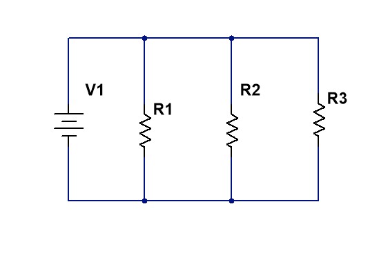
In a parallel circuit, all resistors are connected between the same two nodes, so each resistor receives the same voltage. The source current splits among the branches according to the resistance values: the higher the resistance, the lower the current in that branch. The equivalent resistance of parallel-connected resistors is always less than the smallest individual resistance.
Objectives
- Verify the law of resistors in parallel experimentally.
- Determine the values of individual resistors and the equivalent resistance of the circuit.
Circuit Diagram
Theoretical Law

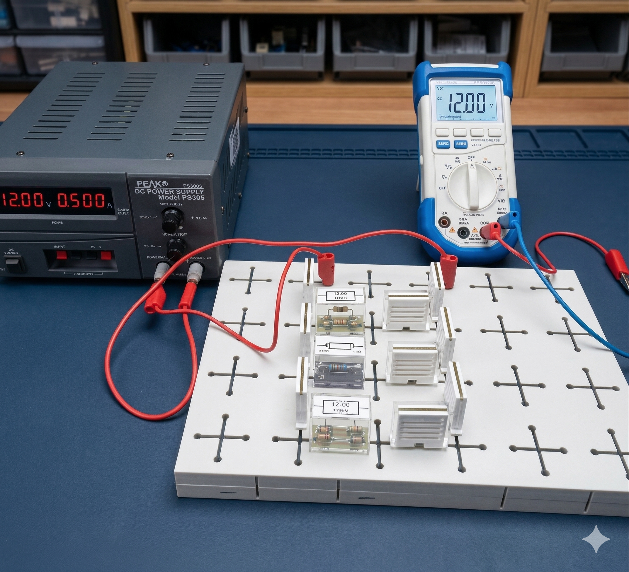
Apparatus
- Resistors of different values.
- Connecting wires.
- Experiment board or breadboard.
- DC power supply.
- Digital multimeter (to be used as voltmeter and ammeter).
Experimental Procedure

Important note:
When measuring voltage, connect the multimeter in parallel with the element.
When measuring current, connect the multimeter in series with the element.
When measuring voltage, connect the multimeter in parallel with the element.
When measuring current, connect the multimeter in series with the element.
Calculations
From the measured values of voltage and current, calculate the resistance of each branch:
- R1 = V1 / I1
- R2 = V2 / I2
- R3 = V3 / I3
- Calculate the equivalent resistance from the parallel law.
- Calculate Rtotal = Vtotal / Itotal.
- Compare the theoretical and experimental results and discuss possible sources of error.
Measurement Table
| Branch | Voltage V (V) | Current I (A) | Resistance R (Ω) |
|---|---|---|---|
| Branch 1 (R1) | V1 = | I1 = | R1 = V1 / I1 |
| Branch 2 (R2) | V2 = | I2 = | R2 = V2 / I2 |
| Branch 3 (R3) | V3 = | I3 = | R3 = V3 / I3 |
| Source (Total) | Vtotal = | Itotal = | Rtotal = Vtotal / Itotal |